
see parts one, two, three, four & five
So now that the revolver is put together and works, I decided I wanted to adapt this 1851 Colt grip frame that I bought on ebay for a pittance to the Blackhawk.
 This is what an 1851 Colt Navy Model looks like (this is an Uberti reproduction, most likely the source of my grip frame)
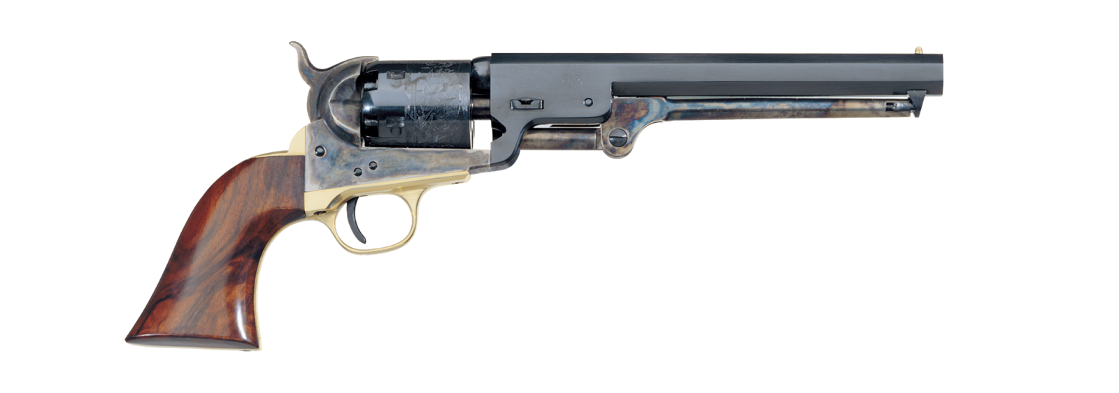

I cannot claim credit for this idea, a gunsmith by the name of Sharps40 did this same modification on a New Model Blackhawk. See the write up here


The process involved:
- making clearance for the Ruger hammer & trigger
- cutting a channel for the trigger return spring
- drilling holes for the trigger return spring pivot and perch locations
- removing some metal for clearance for the main spring
- building a mount for the main strut/spring boss
- drilling a hole in the front trigger guard for the bolt stop spring & plunger
- drilling and installing a pin to locate the grips
- making a custom set of grips from blood wood
We need to add a hole to the back of the trigger slot on the brass frame like the one on the factory aluminum grip frame on the left

Here he is setting up the fixture for drilling the hole


The screw hole in front of the trigger guard had to be filled in. This involved:
- Threading the old hole to accept a larger screw
- The screw was silver soldered in place
- A new hole was drilled and counter-sunk


Here I am filing the trigger slot to make room for the trigger and allow the holes in the Colt grip frame to line up with the Ruger frame. I needed more room side to side and at the front of the slot.

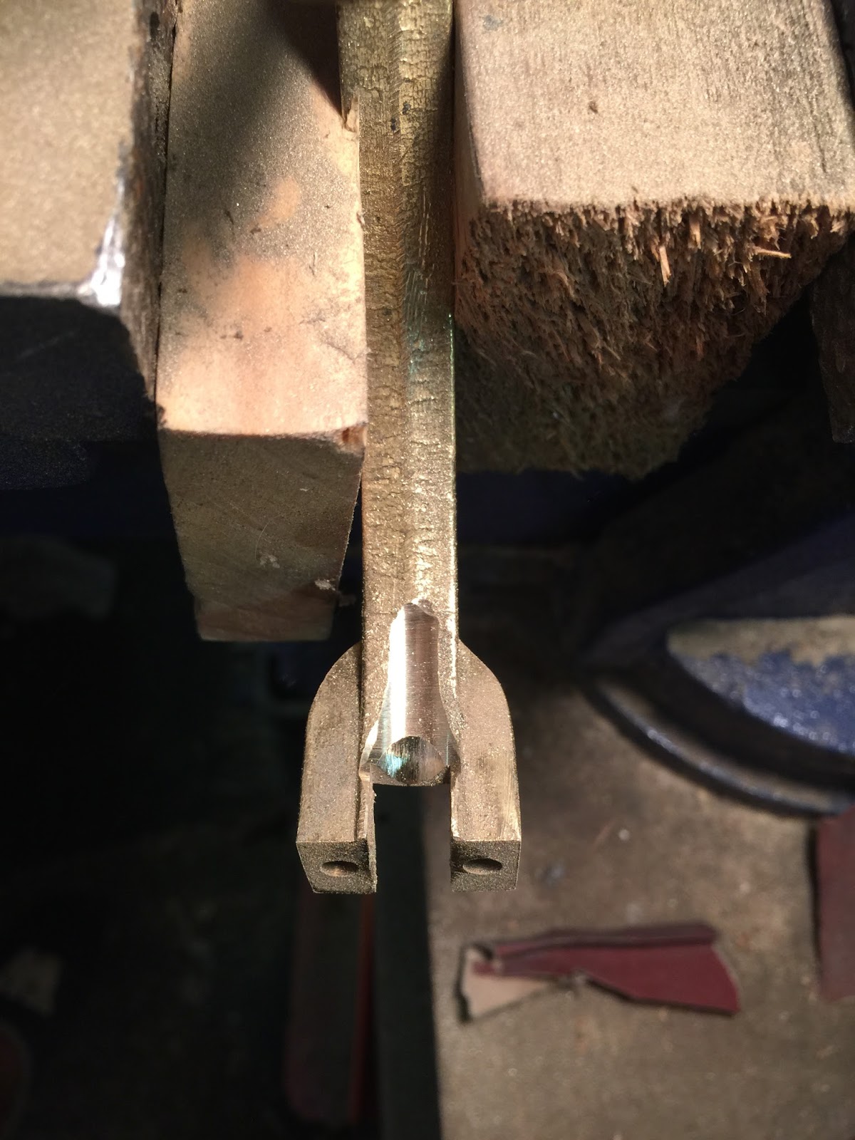
I measured the angle of the main strut on my New Model Single Six. These measurements aren't perfect, but it will get me close to mimicking the factory intended design


I also used my Dremel to make clearance for the main strut/spring assembly in the trigger guard section where the strut passes the apex of the curve


Two things I noticed: 1. The feel of the grip is better than the original Ruger. 2. Something, due to the fit, has taken up all the slop in the action, the gun feels like a brand new revolver.
I marked the grip frame so I could match to the Ruger frame. You can see that the Colt grip frame is slightly proud. I'll have to do this off the gun so as not to risk damaging the finish.

When it comes to the grip panels I had some options. I could buy a grip set for an 1860 Army clone (new or used), split them down the middle and inlet them for my application

Or I could buy and modify this semi-inletted one from Dixie Gun Works


I ordered another one of these grip screw sets from Gun Parts Corp. (same one I used on the Vaquero Bird's Head grips)

Time to make templates for the grip panels, one thing to be wary of is that the top corner where the grip panels meet the Ruger frame, is not a perfect 90 degree corner. I see a lot of grips where a gap is left in this location due to poor fitting. I will try to avoid that

I measured the Colt brass grip frame and compared with the stock Ruger XR3-RED

Next I measured the Ruger grip frame with the factory grips attached (at the widest spot, the heel)

I cut 3/4" wide pieces for the grip panels, I will file/sand them down to get close to the 1.5" overall thickness.
I will fit the top corner 1st, then drill for the locating pin, then fit them to the grip frame

The Ruger's grip locating pin is about .80" wide, I found both 3/4" (.75) and 1" roll pins at the store. I purchased the 1.0" wide ones (1/8 diameter).
The protrusion on the Ruger pin is about .1435" (.80-.513=.287/2=.1435). So I drilled a 1/8" hole, pounded in the 1" roll pin and filed it to .144" protrusion on each side.

I found the rear edge of the trigger frame stuck out a little more than the pistols frame. A small file cleaned it up


I then drilled the 1/8" holes for the dowel pin and the grip screw


No comments:
Post a Comment