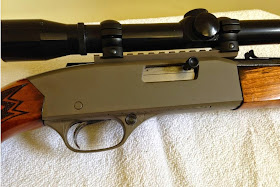
The scope rail on his his Winchester model 290 semi-auto .22 rifle was damaged and he wanted to mount a scope, so he decided to add a standard 20mm picatinny rail to the top of the receiver.
To do this he would need to remove the 11mm scope rail that is cast into the aluminum receiver and figure a way to mount the picatinny rail.
This is what a Winchester model 290 looks like (not his gun)
The pictures and words below are from the Survivor45
First I milled the 11mm scope rail off the top and provided a flat surface for the new picatinny rail.
The section of mil-spec picatinny rail, it only came with one mounting hole....
The tools......
The plans are not only for detailed dimensions but also sometime help with determining the order in which you should do things....
Such as: clearance from internal parts and thicker portions of the receiver. You also need to know how thick your scope base is and how thick your receiver is.
You now know how long your screws will need to be. In the photo there are three dots in the general location of where I will drill the holes.
I want the holes in the scope base to all be in the lower slots of the rail. I have all ready determined the general location in the receiver. Now I will lay out the hole locations relative to the slots in the rail. (white dots)
I will be using a milling machine for the drilling. So I will need to do some "set up".
This is an "edge finder" I will use it to locate my X zero (a stop to the left of the part) and my Y zero (the rear vice jaw).
Starting with the scope base.
What you cannot see in the photo is that my drawing is right in front of me. It shows all the hole locations measured out to .001" . The first hole is at 1.194".
Here is a tip: all drill bits can "wander" off the spot you want the hole.To prevent this I use a center drill to drill a dimple or a "spot". Its the same concept of using a center punch to mark a hole and prevent the drill bit from wandering. All hole locations get "spot drilled"
Last I counter bore for the screw head. This is what makes the screw sit flush with the surface of the scope base.
Mistakes can be made and drill bits do wander. Check your work. If a hole location was off for some unknown reason. It may be possible to move the hole location of the corresponding hole in the receiver.
No mistakes here!
Checking the countersink of the screws
Time to tap. I keep the receiver set up in the mill and install a "spring loaded tap guide".
This keeps the tap perfectly aligned with the hole and adds slight downward spring pressure on the tap.
Looking at the inside of the receiver you can see the holes landed right where Id hoped they would.
The screws are installed, the protrusion is measured so they can be trimmed to length
Completed and assembled. This receiver has some other cosmetic blemishes so a coat of paint and it will look like new.
A coat of Brownell's Aluma-Hyde finishes it off


No comments:
Post a Comment